Searching for Toshiba air conditioner error codes to fix your Toshiba aircon issues?
This guide we offer you the full list of Toshiba air conditioning fault codes that will help you.
Toshiba RAV-SM / RAV-SP aircon error codes
How to check Toshiba RAV-SM / RAV-SP aircon error code?
Toshiba error codes are displayed directly on wired remote controller – to access the service history:
- Press the TEST and the SET button of the remote controller for at least 4 seconds.
- Scroll through stored codes using the TEMP set buttons.
- Then, press the TEST button again to cancel service history.
- The final step is press the CLEAR button to delete codes
A note: Up to 4 Codes can be stored.
| 3 series earlier | 4 series onwards | Possible causes |
|---|---|---|
| E01 | E01 | Controller (local or network) receives no communication from a master indoor unit- could include that master is turned off. Also check that there is a master controller |
| E02 | E02 | Local controller failure (unable to transmit) |
| E03 | E03 | Master indoor unit receives no data to A-B. Often appears as an E01 fault code |
| E04 | E04 | Indoor unit (except twin slave) receives no communication from outdoor unit; can include comprssorer klixon |
| E08 | E08 | Duplicated indoor address |
| E09 | E09 | 2 local controller on a group – both configured as masters |
| E10 | E10 | Indoor PCB failure |
| E18 | E18 | Communication failure between master indoor unit and slave |
| F01 | F01 | Indoor TCJ sensor error |
| F02 | F02 | Indoor TC2 sensor error |
| F04 | F04 | TD Sensor error |
| F06 | TE/TS Sensor error | |
| F06 | TE Sensor error | |
| F07 | TL Sensor Error | |
| F08 | F08 | TO sensor error |
| F10 | F10 | Indoor TA sensor error |
| F12 | TS Sensor Error | |
| F13 | Number of detected IPDU units is reduced | |
| F15 | TE,TS Sensor Error IPDU error | |
| F23 | PS sensor error | |
| F29 | F29 | Indoor PCB failure |
| F31 | Outdoor P.C EEPROM Error | |
| H01 | H01 | Inverter compressor over current detected |
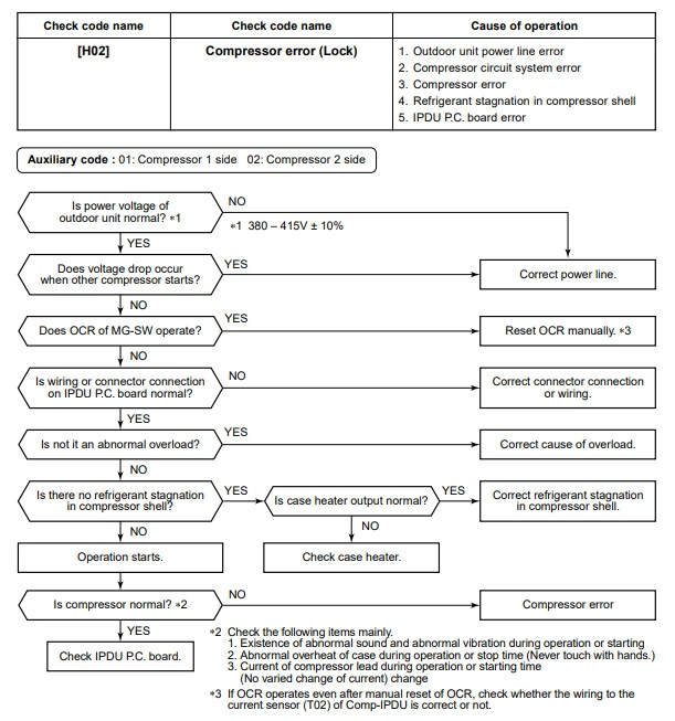
| H02 | H02 | Master outdoor unit over current detected shortly after start up (compressor lock) |
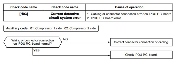
| H03 | H03 | Current detected on master outdoor unit whilst idle |
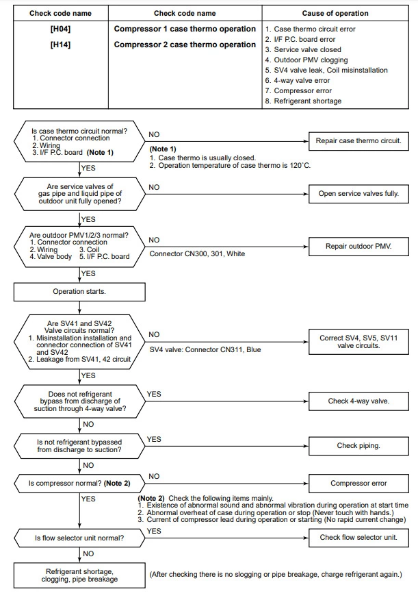
| H04 | Case thermostat operation | |
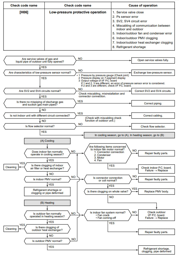
| H06 | H06 | Low pressure detected by Ps sensor (0.02Mpa) |
| L03 | L03 | Duplicated master indoor units in a group |
| L07 | L07 | Indoor in a group previously addressed as a single unit – check addressing |
| L08 | L08 | Indoor address not set |
| L09 | L09 | Indoor unit capacity not set |
| L10 | Unset jumper of service P.C board | |
| L29 | L29 | IPDU error ( number of detected IPDU is reduced ) |
| L30 | L30 | Input on CN80 circuit for 1 minute |
| L31 | L31 | Outdoor PCB error |
| P01 | P01 | Indoor fan motor error |
| P03 | P03 | High discharge temperature (TD1 exceeded 115°C) |
| P04 | P04 | High pressure switch activated (Detected by high TE temp on Digital Inverter) |
| P05 | Open Phase of 3 phase power supply | |
| P07 | P07 | Heat sink overheat Error |
| P10 | P10 | Float switch activated |
| P12 | P12 | Indoor fan motor error – detected by feedback circuit |
| P15 | TD.TS sensor Error | |
| P19 | P19 | Wrong change in temperature (4 way valve error) |
| P20 | TL Sensor error | |
| P22 | P22 | Outdoor fan IPDU error |
| P26 | P26 | Short circuit error of compressor driving element |
| P29 | P29 | Compressor error detected by feedback circuit |
| P31 | P31 | Indoor PCB error |
Toshiba RAS “N” Series aircon error codes
How to check Toshiba RAS “N” Series aircon error code?
Fault codes are displayed through the LEDs flashing at 5 times per second. Note, the green LED will flash once per
second when the system is initially powered.
More specific codes may be obtained, while in the fault mode through the wireless controller.
- Press CHK to enter service mode
- Navigate through TIMER buttons until all LEDs flash, accompanied by the internal buzzer – compare the
displayed code with the table below - Press CLR button to clear the existing fault code (controller displays 7F).
- Press ON/OFF button to exit service mode.
| Light blinking | Error code | Possible causes |
|---|---|---|
| green | 0C | TA sensor open or short circuit |
| green | 0d | TC sensor open or short circuit |
| green | 11 | Indoor fan motor problem |
| green | 12 | Indoor PCB problem |
| green + yellow | 04 | Indoor to outdoor communication (includes compressor thermostat) |
| green + yellow | 05 | Indoor to outdoor communication |
| green + orange | 14 | Inverter low voltage or short circuit protection |
| green + orange | 16 | Compressor position circuit |
| green + orange | 17 | Compressor current detected during off-cycle |
| green + orange | 18 | TE or TS sensor open or short circuit |
| green + orange | 19 | Td sensor open or short circuit |
| green + orange | 1A | Outdoor fan motor problem |
| green + orange | 1b | TE sensor fault |
| green + orange | 1C | Compressor drive circuit |
| green + yellow + orange | 07 | Indoor to outdoor communication (includes compressor thermostat) |
| green + yellow + orange | 08 | Indoor heat exchanger changes temperature – but in wrong direction |
| green + yellow + orange | 1d | Compressor locked rotor current protection |
| green + yellow + orange | 1E | Compressor – high discharge temperature |
| green + yellow + orange | 1F | Compressor current remains too high – after current release |
Caution: must be taken when removing the access covers as high voltages are present.
RAS – Auto Restart Function
The indoor unit is equipped with an automatic restart facility that allows the unit to restart, at the last set operating conditions, after a power failure. The operation will resume without warning three minutes after power is restored. This feature is not set up when these systems are shipped from the factory, therefore it will need to be activated by the installing company.
Generally the process is the same for all RAS products since approx 2001 and is as follows:
To initiate auto restart:
- Turn the power on. Green On/Off light will flash.
- Set the system to operate using the remote controller. Green On/Off light will be on constantly.
- Press and hold down the temporary button for three seconds.
- The indoor unit will bleep three times to acknowledge set up. In most cases the green light changes to orange.
- The system will continue to operate during this set up.
- After set up the system may be stopped using the remote controller.
To cancel auto restart:
- The system is operating. Green On/Off light will be on constantly.
- Stop the system operating using the remote controller. Green On/Off light will extinguish.
- Press and hold down the temporary button for three seconds.
- The indoor unit will bleep three times to acknowledge cancellation.
- The system will have stopped operating.
This feature cannot be set if the timer is in operation. The louver will not swing, if it was previously set, when the system auto restarts.
Toshiba RAV Series aircon error codes
How to check Toshiba RAV Series aircon error code?
Fault diagnosis is available by pressing the check button on the remote controller
- The first number displayed is a code for the number of compressor starts the indoor unit has requested.
- This number is displayed using the hexadecimal format.
- Numbers displayed after the start number are fault codes
| Error code | Possible causes / system status | Check procedure |
|---|---|---|
| 0C | No cooling operation | Sensor Resistance, 20°C = 12.5kΩ, 25°C = 10kΩ |
| 0d | Outdoor unit simulates high temperature release continually | Sensor Resistance, 20°C = 12.5kΩ, 25°C = 10kΩ |
| 04 | No communication outdoor to indoor. Indoor unit operates – outdoor unit does not | – Interconnecting cables / isolator – Outdoor transformer (240/12vac) – Printed Circuit Board |
| 08 | Cooling o/p in Heat mode or heating o/p in Cool mode | Operation of 4 way valve, energised for heating / TC sensor |
| 09 | Indoor fan low speed, no outdoor unit operation | – Gas charge / pipe blockage. – Indoor air flow – TC Sensor / For cross wiring |
| 0b | Indoor water level | Lift pump operation. Condensate drain for blockage. Float switch operation – break on rise |
| 97 | One zone may not be operating | – X&Y terminations and wiring continuity. – Indoor PCB |
| 98 | Duplicated zone address | SW02 address set up |
| 99 | No communication Indoor to Rem. Con. | – Interconnecting cables. – Indoor is set up as a master. – Only one master in a group. |
| 18 | TE Sensor open circuit or short circuit | Sensor Resistance, 20°C = 12.5kΩ, 25°C = 10kΩ |
| 19 | TL or TD Sensor open circuit or short circuit | Sensor Resistance, 20°C = 12.5kΩ, 25°C = 10kΩ, TD 23°C = 53kΩ |
| 20 | Low Pressure Trip | Change Outdoor PCB (No LP Switch) |
| 21 | High Pressure Trip | – Gas Charge – quantity & quality – Pipe blockages – Air flows |
| 1E | High Compressor Discharge Temperature | – Gas Charge – quantity & quality – TD sensor – Indoor unit air flow |
| b5 | External input display fault or Low level refrigerant leak if RD1 fitted | Check connectons on indoor pcb and chech leak detection system if fitted |
| b6 | External interlock display fault or high level refrigerant leak if RD1 fitted | Check connectons on indoor pcb and check leak detection system if fitted |
| b7 | Slave unit in group has fault | Check group controller for faults |
Diagnosis procedure for each error code
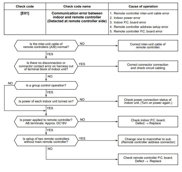
Toshiba error code e01
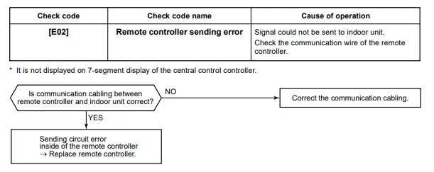
Toshiba error code e02
Toshiba error code e03

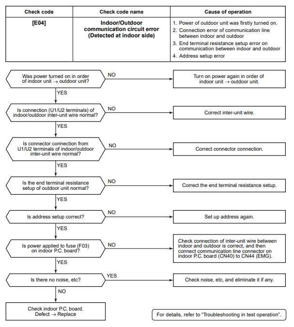
Toshiba error code e04
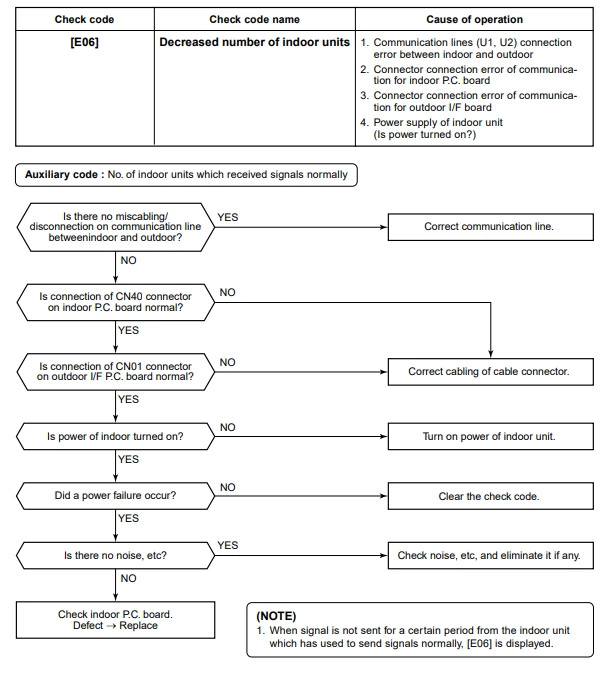
Toshiba error code e06
Toshiba error code e07
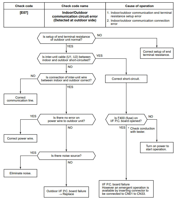
Toshiba error code e08
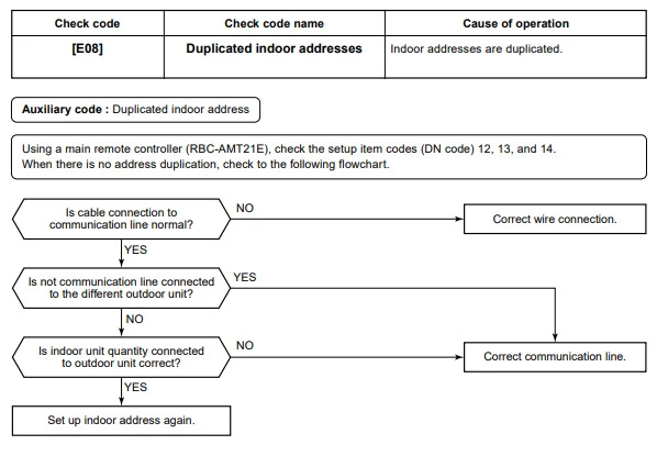
Toshiba error code e09

Toshiba error code e10

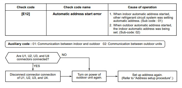
Toshiba error code e12
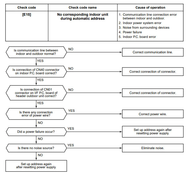
Toshiba error code e15
Toshiba error code e16
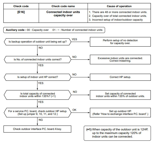
Toshiba error code e18
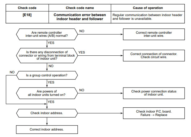
Toshiba error code e19
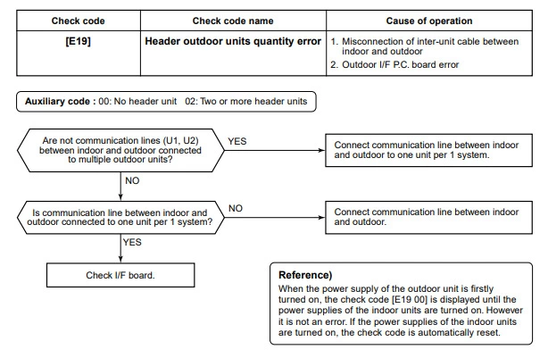
Toshiba error code e20

Toshiba error code e23
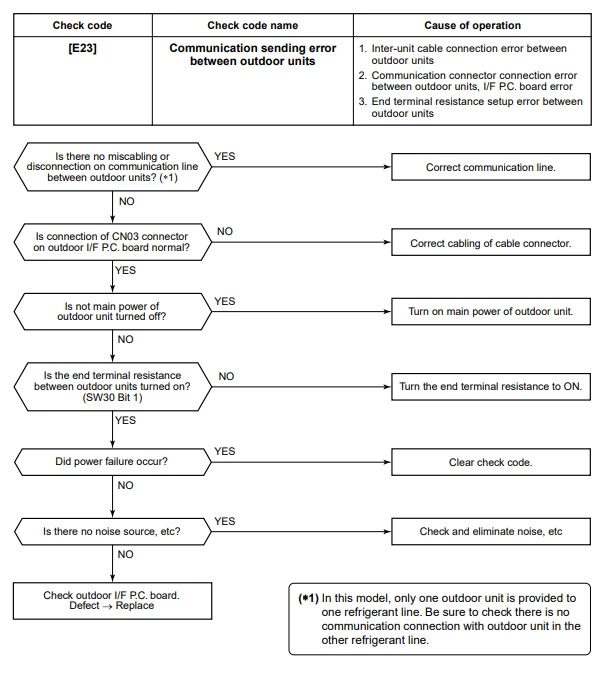
Toshiba error code e25

Toshiba error code e26
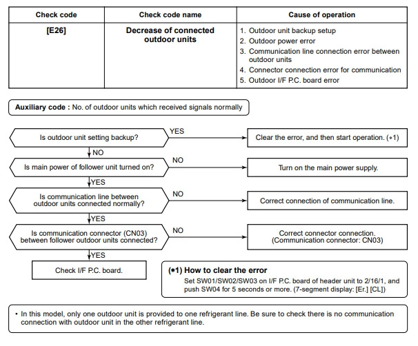
Toshiba error code e28
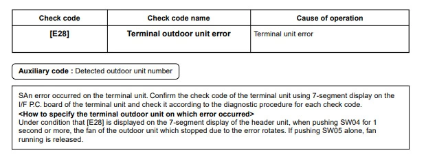
Toshiba error code e31
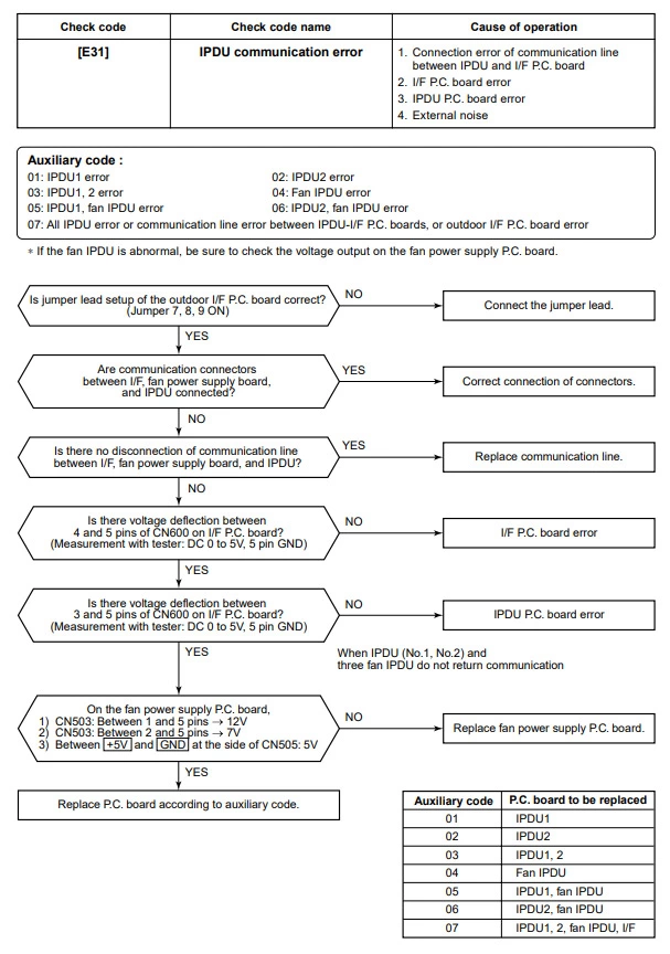
Toshiba error code f01
Toshiba error code f02
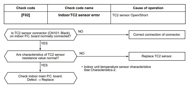
Toshiba error code f03
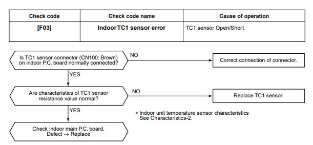
Toshiba error code f04

Toshiba error code f05

Toshiba error code f06

Toshiba error code f07

Toshiba error code f08

Toshiba error code f10

Toshiba error code f12
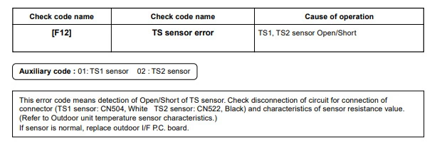
Toshiba error code f13

Toshiba error code f15
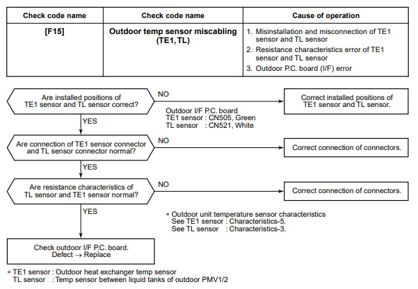
Toshiba error code f16
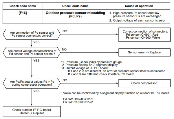
Toshiba error code f23
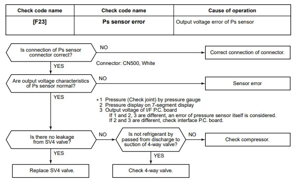
Toshiba error code f24

Toshiba error code f29
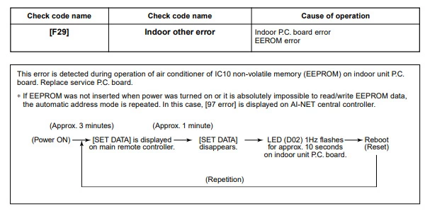
Toshiba error code f31
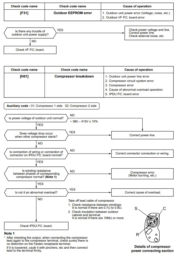
Toshiba error code h02
Toshiba error code h03
Toshiba error code h04
Toshiba error code h06
Toshiba error code h07
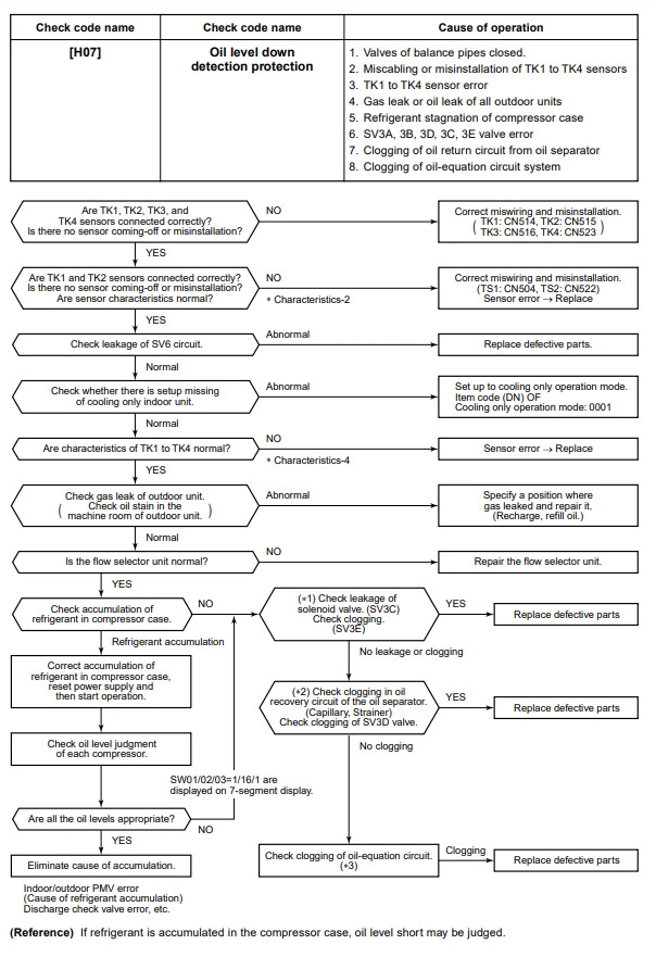
Toshiba error code h08
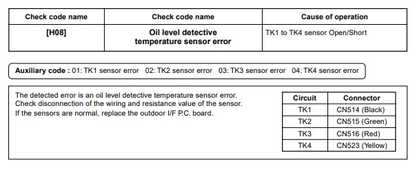
Toshiba error code h16
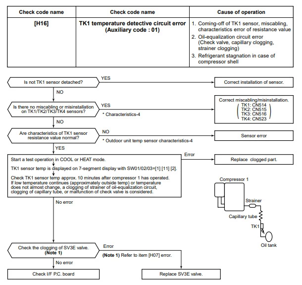
Toshiba error code L03

Toshiba error code L04
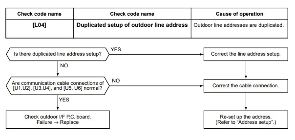
Toshiba error code L05

Toshiba error code L06
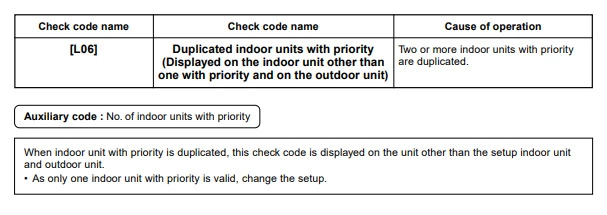
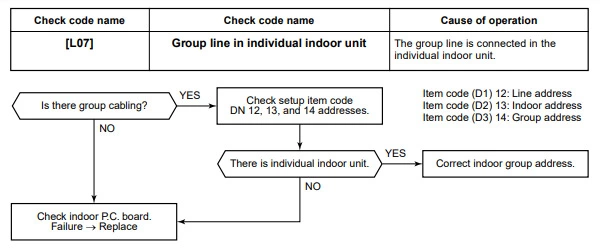
Toshiba error code L07
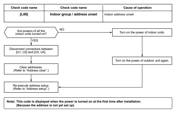
Toshiba error code L08
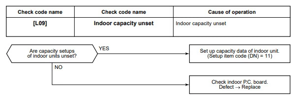
Toshiba error code L09
Toshiba error code L10

Toshiba error code L17
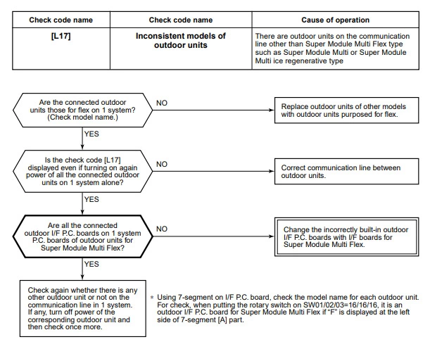
Toshiba error code L18
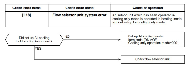
Toshiba error code L20
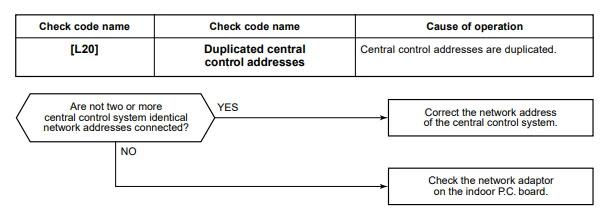
Toshiba error code L28
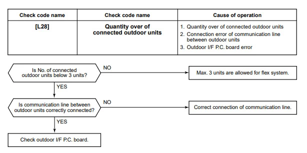
Toshiba error code L29
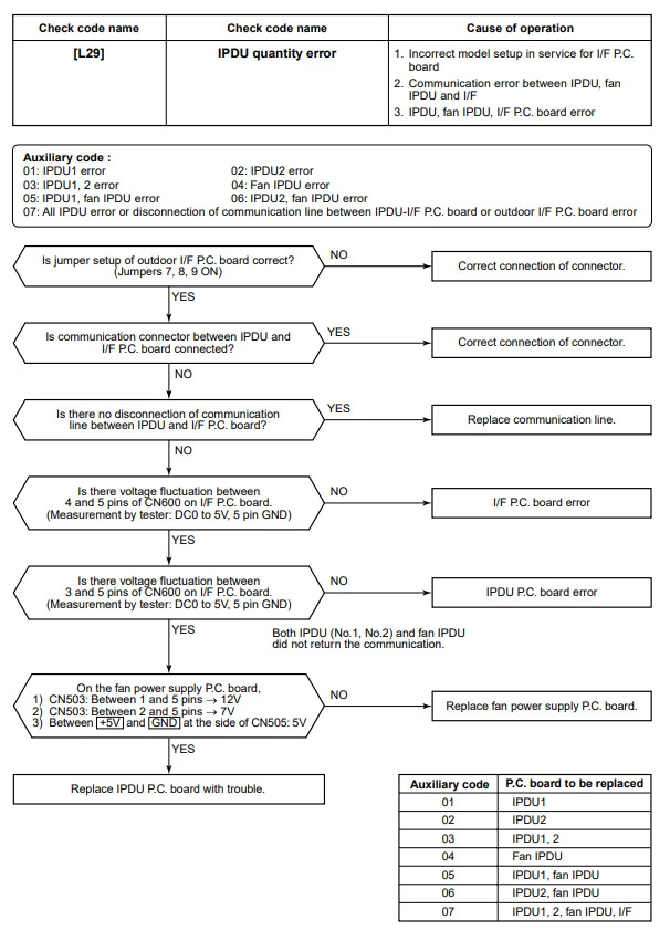
Toshiba error code L30
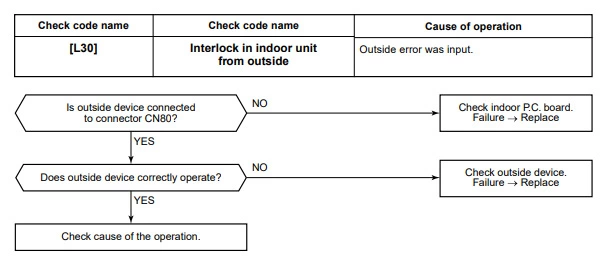
Toshiba error code L31
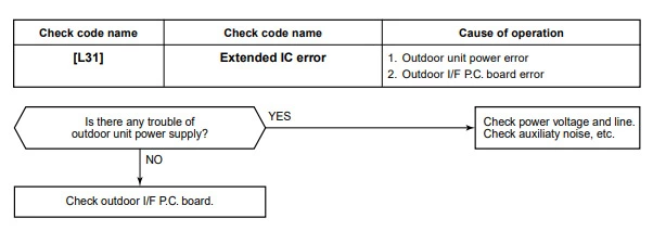
Toshiba error code p01
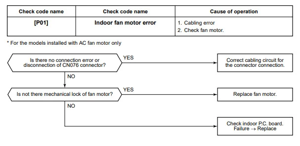
Toshiba error code p03
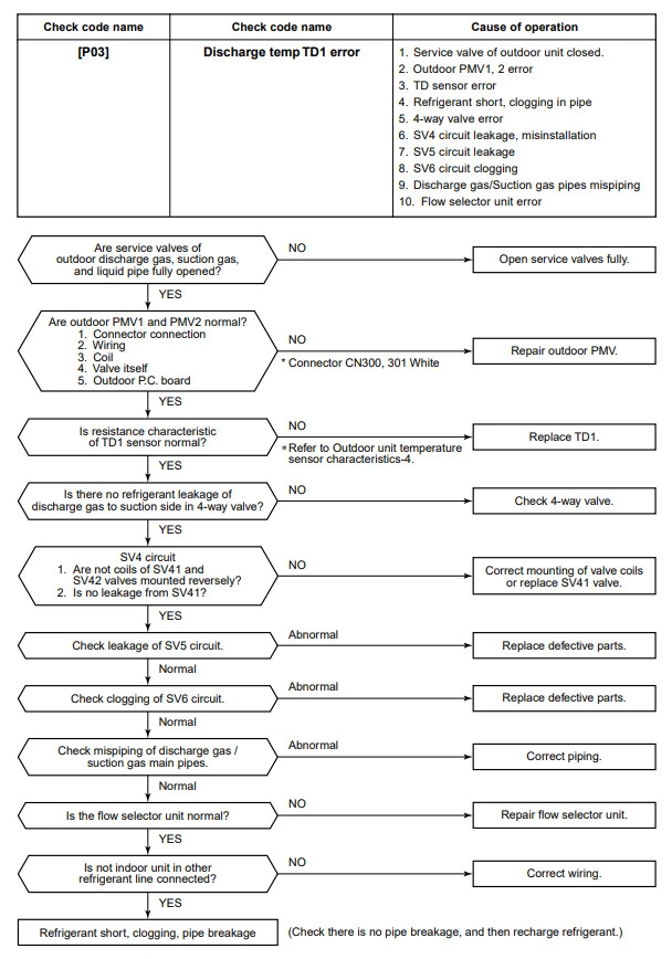
Toshiba error code p04
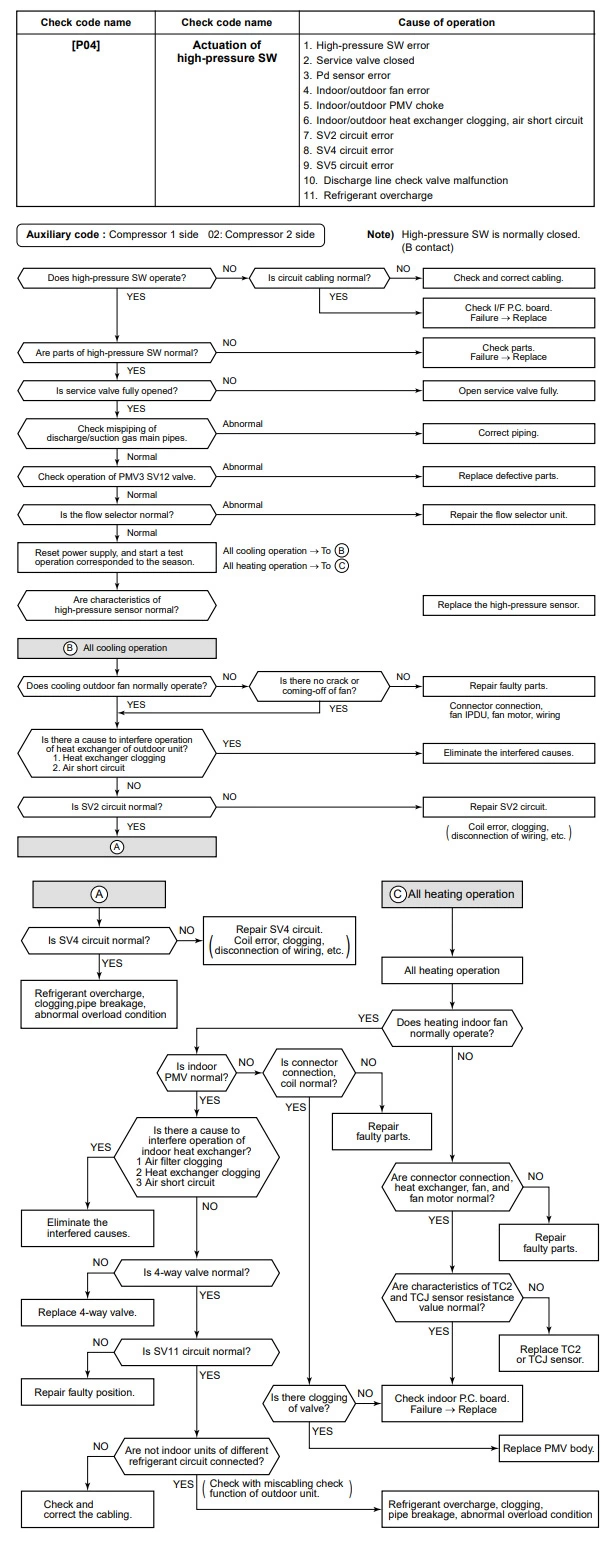
Toshiba error code p05

Toshiba error code p07
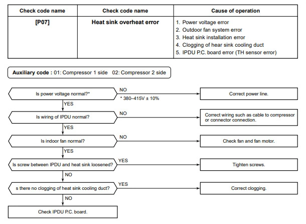
Toshiba error code p10
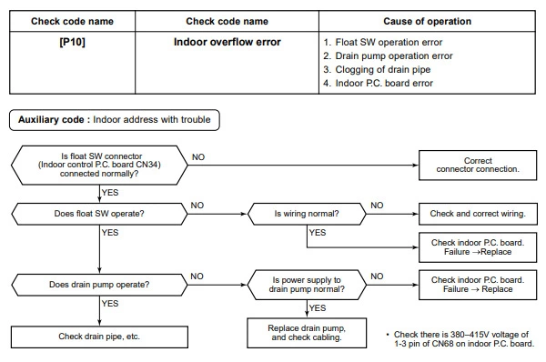
Toshiba error code p12
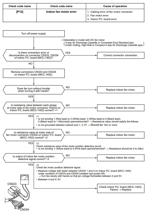
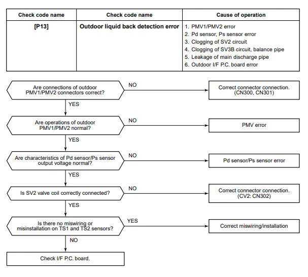
Toshiba error code p13
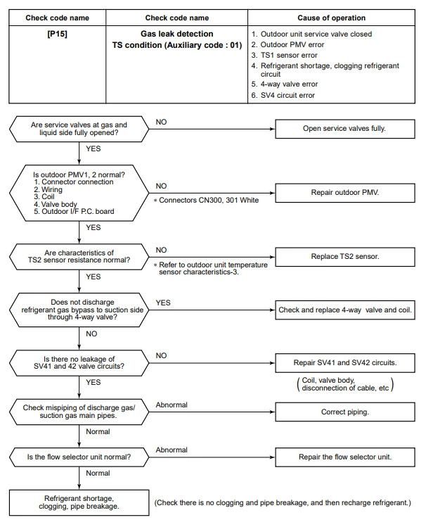
Toshiba error code p15
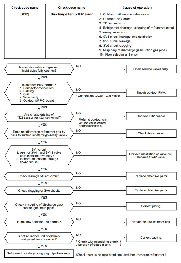
Toshiba error code p17
Toshiba error code p19
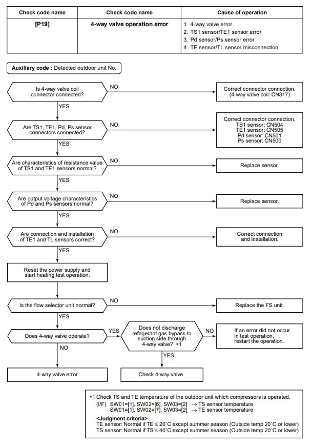
Toshiba error code p20
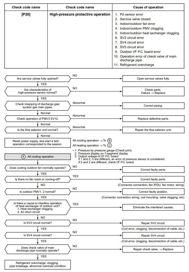
Toshiba error code p22
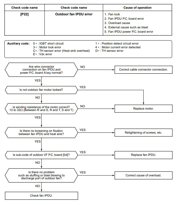
Toshiba error code p26
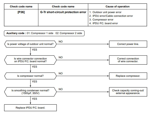
Toshiba error code p29
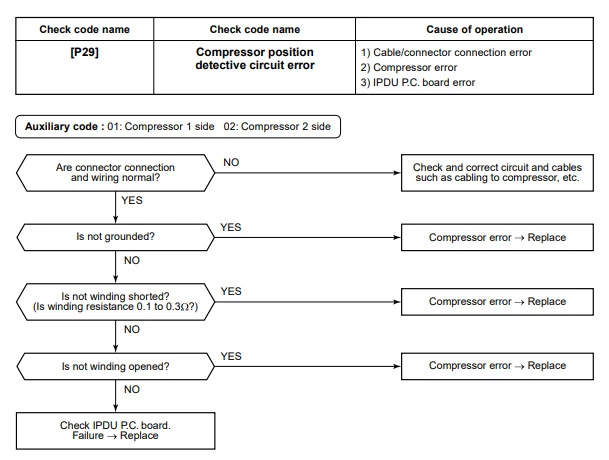
Toshiba error code p31

